Video: https://youtu.be/XtAPtukQDAA
Transcript:
A Triangulated Irregular Network (TIN) mesh is a representation of the surface of the terrain based on a set of points. If you have a site recorder file on hand, you can import spot levels from that file to instantly create a TIN mesh in the drawing area.
- Select Insert > Terrain > Import Site Data, or click on the Terrain toolbar.
- On the first screen of the Terrain Import Wizard, click Browse.
- In the Open dialog, click the drop box next to the File Name edit box and select the file type you are looking for.
- Select the site recorder file you want to import, then click Open. The file is loaded into the Terrain Import Wizard
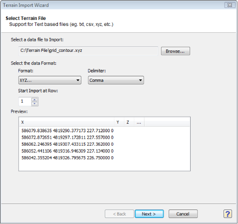
- Click the Format drop box, then select the format of the data that you are importing.
- Click the Delimiter drop box, then select the method used to separate data in the imported file. Choices are Comma, Tab, Space, Semicolon, or Bar/Pipe. If you are not sure what type of delimiter was used in the file, select the option that creates the most optimal result in the preview window. For example, if you are importing an XYZ file, you want to make sure that there is a value displayed in each column (X, Y and Z). If the wrong delimiter is selected, all values may appear grouped into one column (e.g., the X column), and the points will not be input properly.
- If you want to start importing data from a row other than row 1, enter the row number in the Start Import at Row edit box.
- Click Next.
- On the next screen, click the Units drop box and select the unit of measure used in the file that you are importing (Millimeters, Centimeters, Meters, Inches, Feet or Yards).
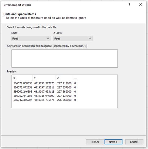
- Certain points in the file may be there as a reference or comment only and should not be included in the import. Such points are usually accompanied by text distinguishing them from the measured spot levels. For example, a point may be labelled as a benchmark rather than a measured spot level. If the file contains points you do not want to import, enter a keyword that identifies them. If you specify multiple keywords, separate them with a semicolon (;). Any lines containing the selected keywords will be ignored when the program imports the file.
- Click Next. The points in the data file are imported into the Wizard. A preview of the resulting mesh is displayed on the next screen. You can zoom and pan in the preview window using the controls below the preview window.
- The overall dimensions of the mesh (Width and Height) are displayed to the left of the preview. The elevation of the highest point on the mesh (the highest Z coordinate) is displayed in the Max Z box, and the lowest point (the lowest Z coordinate) is displayed in the Min Z
- If the resulting values do not look realistic, click Back to select input units that result in correct measurements. Note that the measurements are displayed in the unit of measure selected in your program settings, not necessarily the unit of measure used in the imported file.
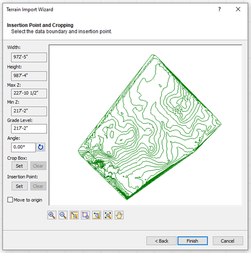
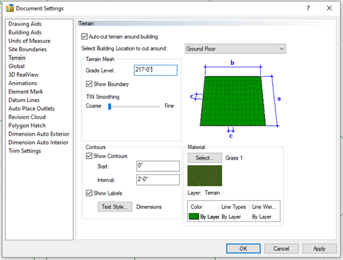
- The Grade Level option allows you to specify the grade level for the model (The height at which all elevations in the model are measured). This value would represent the true heights of the site above sea level. You can adjust the Grade Level depending on where your design will be built within the terrain, but the default will be the lowest Z Value.
- Angle edit box, or click the Pick Angle button next to the Angle edit box and pick two points in the preview window to define the angle. If you are picking points to define the angle, the Angle by Reference dialog appears and reports the angle that you defined. You can edit the angle here if you want.
- If you want to import only a portion of the mesh, click under the Crop Box option, then click two points diagonally in the preview window to define a box around the portion that you want to import. A blue box is displayed around the selected portion. To remove the crop box, click Clear.
- To select a specific insertion point on the mesh, click Set under the Insertion Point option, then select a point on the mesh that you would like to serve as the insertion point. A green circle is displayed at the selected point. This point will be attached to your cursor when you insert the mesh in your drawing area. If you do not select an insertion point, your cursor will be attached to the center of the mesh when you insert it. To remove the defined insertion point, click Clear.
- The Move to origin check box will move the insertion point to the origin specified in the original mesh file.
- Click Finish. The mesh is attached to your cursor.
- Position the mesh in the drawing area, then click to insert it.
- The user may adjust the grade level at any time in Settings > Document Settings, adjusting the position of the model relative to the imported terrain.
- The terrain can also be adjusted by editing the TIN Smoothing slider control. This will smooth out the shape of the terrain. Just note that the smoother you make the terrain the more geometry you will be adding.